5 Phase Stepper Motor Driver Projects
As of January 15, 2018, Site fix-up work has begun! Now do your part and report any bugs or deficiencies. No guarantees, but if we don't report problems they won't get much of a chance to be fixed! Details/discussions at link given just above. 'Some questions have no answers.' [C Baird] 'There comes a point where the spoon-feeding has to stop and the independent thinking has to start.'
[C Lawson] 'There are always ways to disagree, without being disagreeable.' [E Weddington] 'Words represent concepts.
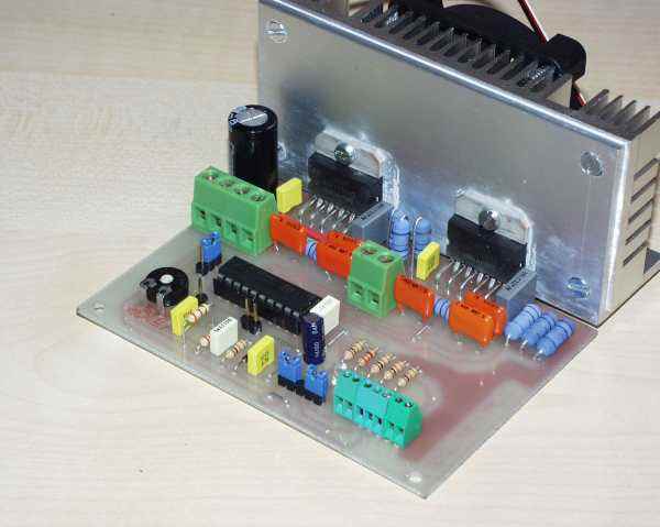
5 Phase Stepper Motor Driver Circuit The compact 5 Phase stepper driver project can handle motor up to 3.5amps supply 12-30V DC, driver has facility to set the load current, driver.
Use the wrong words, communicate the wrong concept.' [J Morin] ' Persistence only goes so far if you set yourself up for failure.' Professor Jones uses a single ended drive in a parallel port. Why do you want to use h-bridge again?
I see you're idea. You turn on one coil, then the one cws from it, and it half steps in between the coils, then just the second coil. So there should be 10 positions. Energizing each winding by itself should give 5 steps of 72 deg each.
So if it really 'halfsteps' between poles with 2 coils on, that scheme with 3 coils on wont do anything. The 2 outside coils cancel. Will be the same as the single coil in the middle. Kod razblokirovki dlya mts modema zte mf 192 1. Quote: I'm no five-phase expert, but why are you energizing all windings at all times? Shouldn't there be some zeroes in that diagram? Each coil (coils 1.5) are connected at one end to positive and the other ends are connected to fets. The individual fets turn on with a '+' Logic high to the gate and turn off with a '-' logic Low to tha gate.
There are no zeros ust on or off. So basically it's 5 bits of information and that is a possible 31 patterns exclude 11111 and 00000 and you have 29 possible states. Unless their is a difference in the polarity of the individual coils. Does it make any difference to turn on a coil in the above picture A-Phase Blue positive and red ground or red positive and blue ground?
If not then with 29 possible states I intend to find the farthest move to the left and the farthest move to the right of this motor. If for example the numbers were 5 and 23 then moving from 5 to 23 should move one step in one direction and moving from 23 to 5 the other direction.
Then there would be just 8 more to figure out to step from 5 up to 23 in 10 steps. I will attempt to measure the distance using a 10 inch circle attached to the motor shaft and mark the 10 steps. Not being a numbers guy I think the possible combinations would be 25 bits but finding the maximum and minimum move of the shaft using 1 to 29 should be easy if I can set up a measuring device unless someone tells me the polarity of turning the coil on is different because then you have many more combinations to the puzzle. The sequence is dictated by the design of the unit. Effectively you have to energise the coils in order to drag the poles of the armature around.
Polarity of the coils is important - one way you're attracting, the other you're repelling. When you're using a h-bridge drive, some coils are pushing, the others are pulling, using a single ended drive, you're just pulling. So, i'd say you'd use a 2-1-2-1. Sequence that is two coils on, then one coil on. The sequence would be: 1 0 0 0 1 If the stepper in question is a permanent magnet type, then the polarity will be important.

Yes Yes Yes finally, i just finished with testing 5 steps 1,2,3,4,5 then I reversed the polarity on 1 and it went one additional step to the right, it's only 10pm now so by 2am i should have this licked. That's right Kartman I was doing that but not doing polarity, Ahhh I see now the coil is wrapped on a bar and one end pushes and the other end pulls when current flows one way and opposit the other way. I guess the drawings of stepper motors I have looked at did not make this clear. I will have to take one apart I think to see it. I would think both polls are used to maximize power but perhaps not, i don't have a clear picture of how the magnets align with the coils and the bar that becomes tha magnet when current is pushed through. I guess that means the circuit i posted above from the other guy that said he got it working is simply wrong because you can't reverse the current using this circuit. So I better work on that.
As of January 15, 2018, Site fix-up work has begun! Now do your part and report any bugs or deficiencies. Snmpc 7 serial number. No guarantees, but if we don't report problems they won't get much of a chance to be fixed! Details/discussions at link given just above. 'Some questions have no answers.' [C Baird] 'There comes a point where the spoon-feeding has to stop and the independent thinking has to start.' [C Lawson] 'There are always ways to disagree, without being disagreeable.'